Filter

Support
Luxor ZD/ZDC

Luxor - Running Cable to the Fixtures

Tabs

Read Article

Once the transformer has been installed and all fixture locations determined, the next step is to run the correct size cable from the transformer to the fixtures. LED fixtures should be provided between 10 and 15 volts AC. This is accomplished by:

  1. Grouping fixtures into distance zones as illustrated below. Do not have a fixture that is 10’ away from the transformer on the same cable run as one that is 100’ away.
  2. Use the proper cabling method for the application. Try to center load all cable runs when possible to minimize the voltage differential between fixtures. 
  3. Use the correct size cable to accommodate voltage drop. As a general rule of thumb, limit the wattage load per each cable run to no more than 100 to 160 watts.
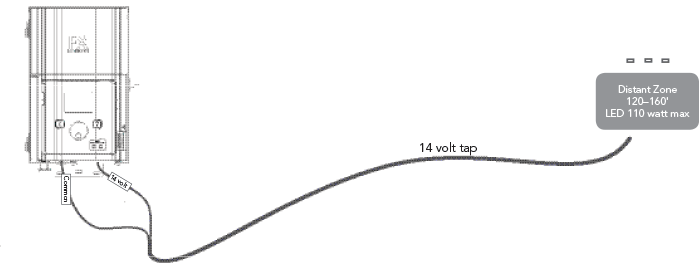
Watts shown are per 12 gauge cable. Install additional cable runs as needed to complete project. To increase wattage maximum, run 8 gauge or double 12 gauge to the first fixture in the zone. Use a digital voltmeter to fine tune circuits.

Summary: For maximum light output and lamp life, each lamp should be provided with between 10 to 15 volts AC. To stay within a 0.5 to 1.0 volt differential between the first light and the last light on a given circuit (while LED lights can support several volts of difference, good design practice is to minimize the voltage difference), you must group the fixtures into distance zones and not overload the cable with excessive wattage. As a rule of thumb, limit the distance between the first fixture and the last fixture on any given run to no more than 50 feet.

Note: Assign all FX ZD fixtures a group number prior to installation. If you are installing the Wi-Fi module and using the LAM, the group numbers for fixtures can be assigned after installation.

LED Wattage Equivalent Chart

 
Specifications 1LED 3LED 6LED 9LED ZDC
Halogen Lumen Output Equivalent 10 watt 20 watt 35 watt 50 watt 20 watt
VA Total 2.4 4.5 13.5 13.5 11.0
Cable Stats

Low voltage lighting systems are typically installed using direct burial rated stranded cable. The most common cable used is referred to as 12/2 stranded cable. The size of cable used in wiring the lighting system will be determined by the wattage load and length of cable run from the transformer to the lighting fixtures. It is very important to note that all low voltage cable has a maximum rating. Overloading cable can create a dangerous safety hazard so be sure to cable your lighting system with the proper size cable.

Low Voltage Cable: Each low voltage lighting cable consists of two parts. One part of the cable is designated to carry the voltage load and is referred to as the Common lead. The Common section is installed into one of the low volt Common lug on the terminal block. The other section is referred to as the 14V lead and is installed into the lugs labeled 14V. Voltage is carried out from the transformer to the fixtures via the Common side of the cable and returns back to the transformer 14V tap via the other half of the cable, thus completing the circuit.

Cabling Methods

Within each cabling zone, you may utilize any of a number of cabling methods. The primary objective is to minimize voltage drop by installing the proper size feeder cable (home run) to each zone, and to make sure each fixture on each cable run is receiving between 10 and 15 volts. Center feeding the “home run” (the main cable run from the transformer to the first fixture on the circuit) will help minimize the voltage differential between the first fixture and the last fixture on the cable run.

Connecting Cables At The Terminal Block

Transformer terminal block – The LUXOR Series Transformer includes one Common lug, and one 14V lug.

Common lugsOne conductor from each cable run coming from the lights to the transformer must be connected to one of the common lugs. The other conductor will be installed into the 14V hot lug. 

Circuit overload – If the amperage load on any given common lug exceeds the transformer capacity the circuit breaker will trip and the display will read “Error Overload”. Test the amperage load on all cables on the common lug using an amp clamp. Test each individual cable on the common lug with the amp clamp. To remedy an overload, reduce the wattage of the system.

Short circuit – The LCD will read “Error Overload” and shut off power if there is a short somewhere in the cabling. This message will continue to be displayed until any button is pressed. To test for a short circuit, check each cable on the common lug. 

Example: A circuit with 100 watts of load should have an amp reading of approximately 8 amps. If the cable is reading significantly more, it has a short somewhere in the cable.

Rate this Article: 
0
No votes yet

Was this article helpful? Yes | No